What Are Flexible Circuits?
Size & Weight Reduction
FPCBs offer significant reduction in weight, thickness, and size compared to rigid PCBs. Very thin dielectrics (down to 1 mil) make them ideal for weight-critical applications.
Dynamic Flexing
Manufactured with high-reliability rolled annealed copper foil for "flex to install" or dynamic flex applications with hundreds of thousands of flex cycles.
3D Packaging
Combining component density of hardboards with flexibility allows designers to achieve routing density not available in traditional boards.
High Reliability
Flexible layers are buried within the board, unlike surface-mounted connectors. Survives high shock (10,000+ G-forces) and vibration.
Cost & Assembly Efficiency
Eliminates wire harnesses and connectors, reducing assembly time and potential failure points. Lower total system cost through simplified design and reduced part count.
Superior Thermal Management
Thin polyimide substrates dissipate heat faster than thick rigid boards. High temperature resistance (up to 200°C) ensures stable performance under thermal stress.
Industry Applications
 Consumer
Consumer Electronics
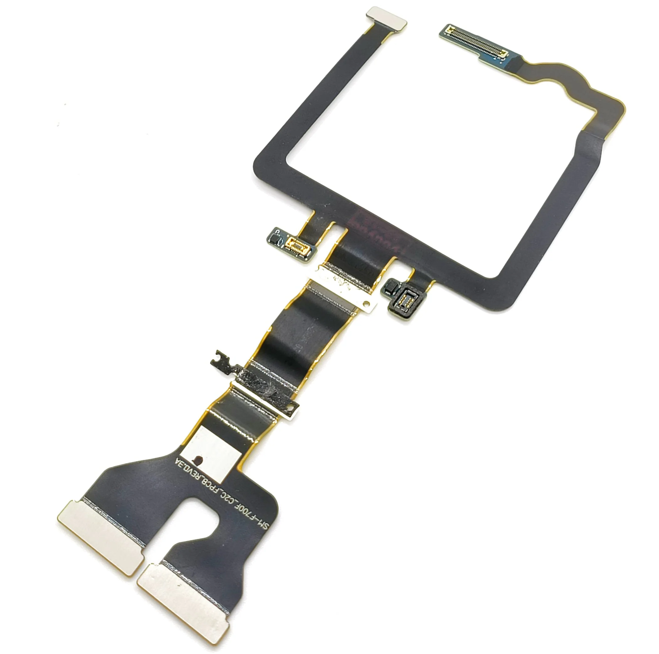
Smartphones, tablets, and laptops utilize FPCs in camera modules, displays, and hinge connections. The ultra-thin profile (0.1mm) enables 3D routing in compact spaces.
 Automotive
Automotive Electronics
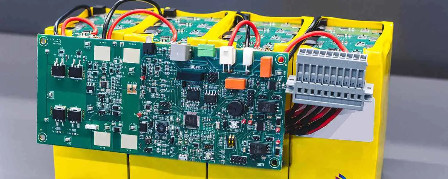
EV battery management systems and infotainment displays rely on FPCs for weight reduction and reliable connections in high-vibration environments.
 Medical
Medical Instruments
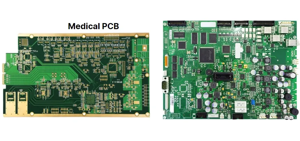
Endoscopes and medical probes use FPCs to transmit HD images through tubes only millimeters wide, navigating complex physiological curves with biocompatibility.
 Aerospace
Aerospace & Drones
Satellites, UAVs, and spacecraft use rigid-flex circuits for extreme weight savings and reliability in high-shock (10,000+ G) launch environments.
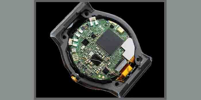 Wearable
Wearable Devices
Smartwatches and fitness trackers utilize FPCs to bend around curved surfaces, connecting sensors and displays while withstanding repeated wrist movement.
 Industrial
Industrial Automation
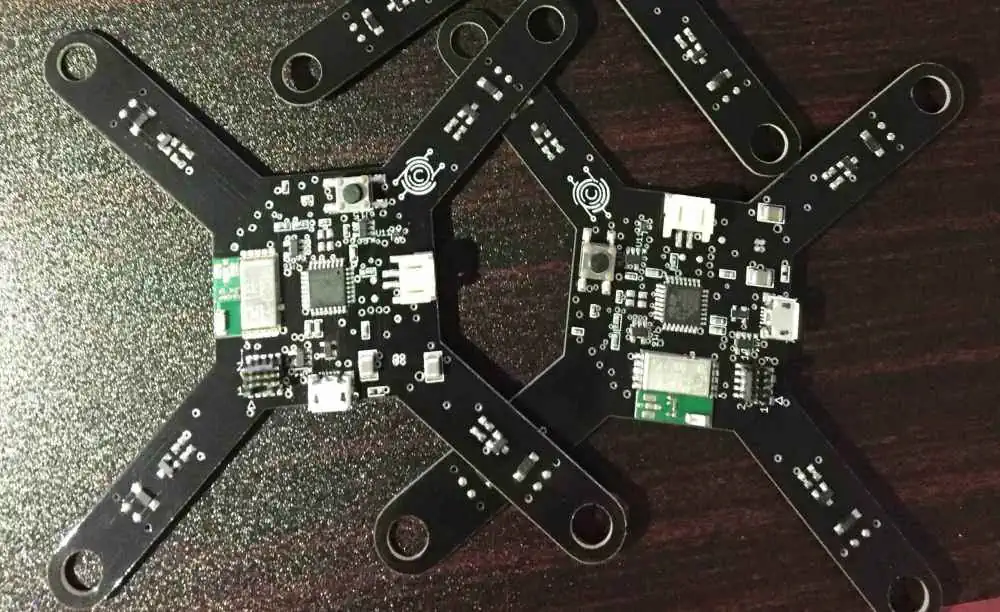
Robotic arms and automation equipment use FPCs for continuous flexing in moving joints, replacing fragile wire harnesses that fail under constant motion.
Flex Circuit Construction Types
Consisting of a single thin conductive layer, hot-pressed with flexible dielectric film.
- ✓Most basic and common type
- ✓Electrical insulation and protection
- ✓Minimum thickness: 2.75mil
Polyimide base with conductive layers on both sides, interconnected by PTH.
- ✓Two conductive layers
- ✓Plated Through Holes
- ✓Minimum thickness: 5.0mil
Three or more conductive layers combining constructions.
- ✓Adhesive layers for bonding
- ✓Interconnected by plated vias
- ✓Up to 20+ layers
Laminating flexible and rigid substrates together.
- ✓Rigid parts carry components
- ✓No soldering between sections
- ✓High shock/vibration resistant
Benefits vs Traditional PCBs
Performance Benefits
-
✓Superior Heat Dissipation
Better thermal management -
✓Dynamic Flexing
Hundreds of thousands of cycles -
✓Lower Inductance
Reduced signal loss -
✓Package Density
Higher density in smaller spaces
Cost & Reliability
-
✓Error Elimination
Replaces miswired harnesses -
✓Improved Reliability
Buried layers vs surface connectors -
✓Reduced Assembly
Less labor required -
✓Weight Savings
Critical for aerospace/drones
Manufacturing Capabilities
| Parameter | Specification | Notes |
|---|---|---|
| Layer Counts | 1-4 Flex / Up to 20+ Rigid-Flex | Flexible layers typically 1-4 |
| Copper Thickness | 0.5oz - 2oz | Standard and heavy copper |
| Min PCB Size | 0.4" x 0.4" | Max: 8.65" x 19.65" |
| Min Thickness | 1 Layer: 2.75mil / 2 Layer: 5.0mil | Very thin dielectrics |
| Trace Width/Space | 3.0/3.0mil (min) | Varies by copper weight |
| Lead Time | 14 days (2-layer) | Quick-turn available |
When Should You Use Rigid-Flex PCBs?
Frequently Asked Questions
A Flexible PCB (FPC) is a circuit board made from flexible substrate materials like polyimide (Kapton). Unlike rigid boards, flex PCBs can bend, fold, and conform to 3D shapes, making them ideal for compact electronics, wearables, medical devices, and applications requiring dynamic flexing or space-saving designs.
Flex PCBs are entirely flexible throughout, while Rigid-Flex PCBs combine rigid FR-4 sections with flexible polyimide sections in a single board. Rigid-flex boards are ideal when you need stable component mounting areas (rigid parts) connected by flexible circuits, eliminating connectors and reducing assembly complexity and weight.
For prototype flex PCBs, our express service delivers in as fast as 5 business days. Standard prototype orders ship in 7-10 days. Production orders typically range from 10-20 days depending on complexity, layer count, and quantity. Rush options are available for urgent projects with additional expedite fees.
Simply fill out our online quote form with your specifications (layers, size, quantity, surface finish, etc.) or email your Gerber files directly to quote@flextechcircuits.com. We provide detailed quotes within 2 hours during business hours. For complex designs, our engineers will review and provide pricing with DFM recommendations.
We accept Gerber RS-274X files (preferred), ODB++, Excellon drill files, IPC-2581, and most major EDA exports including Altium Designer, Eagle, KiCad, OrCAD, and PADS. Our free DFM (Design for Manufacturing) check will identify any potential manufacturability issues before production begins.
How It Works & Simple 5-Step Process
Request Quote
Fill out the online form with your PCB specifications
Upload Files
Send us your Gerber or design files via email
DFM Review
Free Design for Manufacturing check by our engineers
Production
ISO-certified manufacturing with quality control
Delivery
Fast worldwide shipping via DHL, FedEx, UPS
Ready to Start Your Flex PCB Project?
Get a free quote within 2 hours. Free DFM check included with every order. No minimum order quantity required for prototypes.