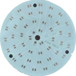
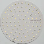
What is LED PCB?
LED PCB (Light Emitting Diode Printed Circuit Board) is a specialized type of metal core PCB (MCPCB) designed specifically for LED applications. Unlike standard FR-4 PCBs, LED PCBs use a metal base substrate — typically aluminum or copper — to efficiently dissipate heat generated by high-power LEDs.
The structure consists of three main layers: (1) Circuit layer (copper foil with LED circuits), (2) Thermal conductive dielectric layer (insulating but thermally conductive material), and (3) Metal base layer (aluminum or copper for heat spreading).
In 2026, with the explosive growth of automotive LED lighting, smart city LED street lights, horticultural LED grow lights, and Mini/Micro LED displays, LED PCB technology has advanced to support thermal conductivity up to 8.0 W/m·K and multi-layer hybrid designs combining FR-4 + metal core for complex LED driver circuits.
LED PCB Manufacturing
Aluminum & Copper Base PCB • Thermal Conductivity up to 8.0 W/m·K • 2026 Edition
LED PCB Types & Base Materials (2026 Edition)
LED PCB Types Overview
| LED PCB Type | Base Material | Thermal Conductivity | Typical Application |
|---|---|---|---|
| Aluminum PCB | AL5052, AL6061 | 1.0 - 3.0 W/m·K | LED bulbs, LED tubes, LED panels |
| High Thermal Aluminum PCB | AL with ceramic filler | 3.0 - 5.0 W/m·K | LED street lights, high bay lights |
| Copper Base PCB | Pure Copper (C1100) | 5.0 - 8.0 W/m·K | Automotive LED headlights, stadium lighting |
| Hybrid LED PCB | FR-4 + Aluminum | 1.5 - 2.0 W/m·K | LED drivers with integrated control circuits |
| Ceramic PCB (DBC) | AlN, Al₂O₃ | 15 - 180 W/m·K | COB LED, Mini/Micro LED displays |
← Swipe left/right to view full table →
Base Material Comparison (2026)
| Property | Aluminum 5052 | Aluminum 6061 | Copper C1100 | Ceramic AlN |
|---|---|---|---|---|
| Thermal Conductivity | 138 W/m·K | 167 W/m·K | 400 W/m·K | 180 W/m·K |
| Density (g/cm³) | 2.68 | 2.70 | 8.96 | 3.30 |
| Cost Level | $ | $$ | $$$ | $$$$ |
| Best For | General LED | High-power LED | Automotive LED | COB/Mini LED |
← Swipe left/right to view full table →
Our LED PCB Manufacturing Capabilities (2026 Upgraded)
Layer Count & Thickness
- Single Layer: 0.8mm - 3.0mm
- Double Layer: 1.0mm - 3.0mm
- Multi-layer (4-6L): Hybrid design
- Base Thickness: 1.0mm, 1.5mm, 2.0mm, 3.0mm
Thermal Conductivity Range
- Standard: 1.0 - 1.5 W/m·K
- High Thermal: 2.0 - 3.0 W/m·K
- Ultra-High: 4.0 - 5.0 W/m·K
- Extreme (Copper): 6.0 - 8.0 W/m·K
Copper Thickness Options
- 1 oz (35 μm): Standard LED
- 2 oz (70 μm): Mid-power LED
- 3 oz (105 μm): High-power LED
- 4-10 oz: Automotive LED
Surface Finish Options
- HASL: Cost-effective
- Lead-Free HASL: RoHS compliant
- ENIG: Gold plating for wire bonding
- OSP: Solderability protection
Solder Mask Colors
- White: High reflectivity (90%+)
- Black: Premium appearance
- Green: Standard option
- Custom: Blue, Red, Yellow
Board Size Range
- Minimum: 10mm × 10mm
- Maximum: 500mm × 600mm
- Standard: Custom sizes
- Panel: Multi-up array supported
LED PCB Technical Specifications (2026 Standard)
| Parameter | Specification |
|---|---|
| Base Material | Aluminum 5052/6061, Copper C1100, Ceramic AlN/Al₂O₃ |
| Layer Count | 1-6 layers (1-2L standard, 4-6L hybrid) |
| Board Thickness | 0.8mm - 3.0mm (standard: 1.0mm, 1.5mm, 2.0mm) |
| Copper Thickness | 1oz - 10oz (35μm - 350μm) |
| Thermal Conductivity | 1.0 - 8.0 W/m·K (dielectric layer) |
| Dielectric Breakdown | ≥3000V AC (1 minute test) |
| Insulation Resistance | ≥100 MΩ (500V DC) |
| Minimum Trace/Space | 0.15mm / 0.15mm (6mil/6mil) |
| Minimum Hole Size | 0.25mm (plated), 0.20mm (non-plated) |
| Solder Mask | White (high reflectivity), Black, Green, Custom colors |
| Surface Finish | HASL, Lead-Free HASL, ENIG, OSP, Immersion Silver |
| Max Board Size | 500mm × 600mm (19.7" × 23.6") |
| Operating Temperature | -40°C to +125°C |
| Certifications | UL, IATF16949, ISO9001, RoHS, REACH |
| Lead Time | 24 hours (prototype), 5-7 days (production) |
← Swipe left/right to view full table →