PCB Assembly Quality Inspection Methods
In the rapidly evolving world of electronics, ensuring the quality of Printed Circuit Board (PCB) assemblies is paramount. Quality inspection methods play a critical role in maintaining the integrity and functionality of electronic devices. This article delves into various PCB assembly quality inspection methods, highlighting their importance, techniques, and best practices.
Understanding PCB Assembly Quality Inspection
PCB assembly quality inspection refers to the systematic evaluation of the assembled PCB to confirm that it meets the specified requirements and standards. This process is essential for identifying defects early, reducing costs, and ensuring product reliability. The inspection methods can be classified into several categories:
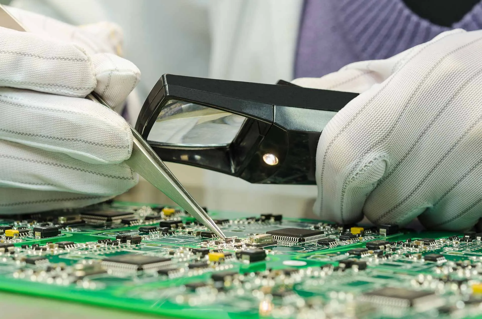
1. Visual Inspection
Visual inspection is often the first step in the quality control process. It involves a thorough examination of the PCB surface and components for any visible defects.
- Manual Inspection: Trained inspectors visually check the PCBs for soldering defects, component placements, and overall board condition.
- Automated Optical Inspection (AOI): Utilizing cameras and software, AOI systems automatically scan PCBs for defects, ensuring faster and more consistent inspections.
2. Electrical Testing
Electrical testing assesses the functionality of the PCB by measuring the electrical characteristics of the components. Common methods include:
- In-Circuit Testing (ICT): This method tests individual components on the PCB while in-circuit, allowing for the detection of shorts, opens, and incorrect component values.
- Functional Testing: This involves testing the entire PCB under normal operating conditions to ensure it performs as intended.
3. X-Ray Inspection
X-ray inspection is particularly useful for detecting hidden defects, such as voids in solder joints and issues in multi-layer boards. This non-destructive testing method provides detailed images of the internal structures of the PCB.
4. Solder Joint Inspection
Ensuring the quality of solder joints is critical for the reliability of electronic assemblies. Inspection methods include:
- Cross-Sectional Analysis: This destructive test involves cutting the PCB and examining the solder joints under a microscope to evaluate their quality.
- Thermal Imaging: This technique uses infrared cameras to detect heat patterns, helping identify solder joint issues based on thermal performance.
5. Environmental Testing
Environmental testing evaluates how PCBs perform under various environmental conditions, ensuring they can withstand factors such as humidity, temperature fluctuations, and vibration.
Best Practices for PCB Assembly Quality Inspection
Implementing effective inspection methods is only part of ensuring quality. Here are some best practices to enhance your PCB assembly quality inspection process:
- Establish Clear Standards: Define clear quality standards and specifications for inspections to ensure consistency across all teams.
- Utilize Advanced Technology: Invest in modern inspection technologies like AOI and X-ray inspection to improve accuracy and efficiency.
- Regular Training: Conduct regular training sessions for inspection personnel to keep them updated on the latest techniques and technologies.
- Implement a Feedback Loop: Create a system for feedback from inspections to improve manufacturing processes continuously.
- Document Everything: Maintain detailed records of inspections to help identify trends and areas for improvement.
Conclusion
Quality inspection methods are vital in the PCB assembly process, ensuring that electronic devices function reliably and meet industry standards. By employing a combination of visual inspection, electrical testing, X-ray inspection, solder joint evaluation, and environmental testing, manufacturers can significantly reduce defects and enhance product quality. By following best practices and continually improving inspection methods, companies can stay competitive in the rapidly changing electronics market.